
Optimizing Gear Rack Assembly To Maximize Positioning Accuracy
 The positioning accuracy of a rack & pinion drive is dependent on the cumulative pitch error inherent in each gear rack used. For long travel lengths, this cumulative pitch error can add up very quickly and dramatically affect the positioning accuracy of the axis.
ATLANTA now offers “digital” gear racks and an Industry 4.0 smartphone website that when used together can optimize the assembly of a multi gear rack system to minimize the cumulative pitch error and maximize positioning accuracy over the complete axis travel length.
Understanding Gear Rack Accuracy
Gear racks, like any other mechanical component, have tolerances associated with their dimensions. The linear accuracy of a gear rack depends on the accuracy of its teeth in relation to each other, also known as pitch error or pitch deviation. There are typically three levels of pitch error seen:
- High pitch error: Gear racks with hardened teeth, due to the tooth deformation that occurs during the hardening process. Typical error of 0.20 mm per meter.
- Medium pitch error: Gear racks with milled teeth. Typical error of 0.10 to 0.15 mm per meter.
- Low pitch error: Gear racks with ground teeth, with the grinding achieving very precise teeth. Typical error of less than 0.05 mm per meter.
For long travel axis, multiple pieces of gear rack are mounted end-to-end to achieve the desired axis length. The positioning accuracy of the complete axis is dependent on the cumulative pitch error of all the gear racks in the axis. For long travel lengths, this cumulative pitch error can add up very quickly and dramatically affect the positioning accuracy of the axis.
So how can you achieve precision positioning on a long travel axis without accumulating pitch error? In the past, the only way to remove axis positioning errors was to measure the complete axis with a laser interferometer and then compensate for any errors seen with the servo motor software. This was a costly and time consuming method for error removal.
The latest manufacturing innovations can achieve precision long travel axis by measuring and “mapping” the gear racks and optimally assembling them to effectively cancel out the gear rack pitch error. Let’s start by defining what “mapping” a gear rack means.
The Birth Of The “Digital” Gear Rack
“Mapping” gear racks means to measure all of the gear racks to be used on an axis to determine their individual pitch error and use this information to create an optimal assembly “map” so that the total cumulative pitch error of the axis can be reduced or cancelled out entirely.
The exact pitch error of each gear rack is determined by measuring every rack after it is manufactured. A linear measuring machine is used to precisely measure pitch error, along with other dimensional tolerances. Depending on the manufacturing process, the pitch error may vary plus or minus its theoretical value.. So a 2,000 mm long rack could actually measure slightly more or less than that value.
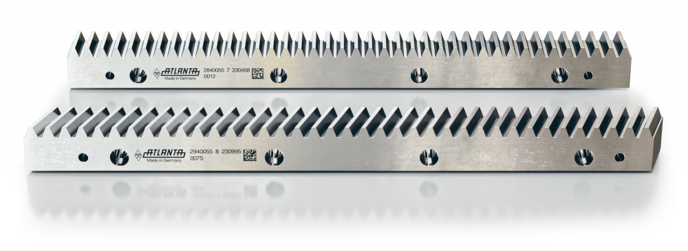
To document the gear rack pitch error value for future use and to allow for automation of the gear rack mapping procedure, a 2D matrix code (similar to a QR code) and serial number is engraved directly onto the gear rack itself. This transforms an ordinary gear rack into a “digital” gear rack with smart drive technology built in.
This transformation is also known as Industry 4.0, which is a German government initiative being called the next industrial revolution. It involves integrating people, product and machines to control processes and expand flexibility. The manufactured product, environmental variables and machine variables are tracked, measured, analyzed and controlled throughout the manufacturing process using smart devices or sensors.
Creating An Optimal Assembly Map For The Gear Racks
The “digital” gear rack marked with the 2D matrix code can now be used with the ATLANTA Industry 4.0 smartphone website to create an assembly map. This website allows a customer to scan the 2D matrix code on the gear racks and download the encoded manufacturing information from the Cloud. This information can be used to create an assembly map for the gear racks.
For a desired travel axis length, a series of gear racks would be set out to be scanned. Each gear rack would be scanned into the website, which would collect all of the gear rack pitch error information into the mapping tool. Once all of the gear racks have been scanned, the website would sort the gear rack assembly order to achieve the minimum cumulative pitch error and maximum positioning accuracy for the total axis length. This would be best illustrated with an example:
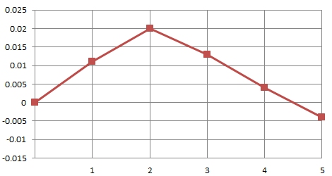
A machine builder has a ten meter long axis that they would like to optimize for precise positioning over the entire length. Using five pieces of a two-meter helical module 3.0 hardened & ground rack, they randomly scanned the racks with the smartphone website, which showed:
- Rack #1, Pitch Error: +0.011 mm
- Rack #2, Pitch Error: +0.009 mm
- Rack #3, Pitch Error: -0.007 mm
- Rack #4, Pitch Error: -0.009 mm
- Rack #5, Pitch Error: -0.008 mm
If the racks were assembled in this order, the total cumulative pitch error for the axis would range from -0.004 mm to +0.020 mm.
Total Axis Pitch Error Before Rack Sorting
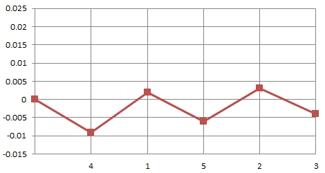
Using the mapping tool on the website, it would recommend the following optimal rack assembly order:
- Rack #4, Pitch Error: -0.009 mm
- Rack #1, Pitch Error: +0.011 mm
- Rack #5, Pitch Error: -0.008 mm
- Rack #2, Pitch Error: +0.009 mm
- Rack #3, Pitch Error: -0.007 mm
For the total axis length, the total cumulative pitch error would range from -0.009 mm to +0.003 mm. This would be optimal because the total error would never be more than 0.009 mm away from the theoretical “zero” rack position, which is a reduction in total error of over 50%.
Total Axis Pitch Error After Rack Sorting
The mapping tool can significantly reduce the maximum positioning error seen along the entire axis travel length. This can be very helpful for machines with longer travel lengths, allowing for significant machine performance and precision improvements with increased assembly efficiency using standard, off-the-shelf ATLANTA rack & pinion products.
Additional Benefits of Mapping “Digital” Gear Racks
Besides positioning errors, gear rack pitch error can also cause alignment issues between the rack mounting holes and the tapped holes in the machine frame. Because mounting holes are typically located to the gear teeth, if the gear teeth have pitch errors, the mounting hole locations will inherit the same errors.
By mapping the gear racks to minimize the cumulative pitch error, the mounting holes locations are also kept in check so that they will always line up with the tapped holes in the machine frame. In some cases, it could be possible to reduce the required quality of the rack, which would allow a more economical rack to be used while still optimizing the cumulative pitch error.
Customers can also scan and sort gear racks they have in stock for a series of machines. This allows the customer to best use their gear rack stock to optimize several machine builds at once.
Another benefit of using the “digital” gear rack is if a rack is damaged and needs to be replaced, it would be possible to get a replacement rack with similar pitch error. This would allow the rack to be replaced without the need to adjust or disrupt any of the other gear racks on the axis.
Conclusion
By utilizing ATLANTA “digital” gear racks and the ATLANTA Industry 4.0 website, it is now possible to optimize the assembly of a multi gear rack system to minimize the cumulative pitch error and maximize positioning accuracy over the complete axis travel length. With these new technologies, it is no longer needed to use costly and time consuming servo compensation to correct axis errors.
Machine builders can now enter the world of smart drive technology, allowing for significant machine performance and precision improvements with increased assembly efficiency using standard, off-the-shelf ATLANTA rack & pinion products.
For more information, contact ATLANTA Drive Systems at: (800) 505-1715, or on the web at: www.atlantadrives.com.